DMX-iT
- Details
- Written by: Super User
- Hits: 113663
|
|
Engineering and Sales
Integrated Controls, Inc. Shipping Address2851 21st St.San Francisco, CA 94110
|
Disclaimer
Prices, specifications, features and availability subject to change without notice
- Details
- Written by: Super User
- Hits: 10495
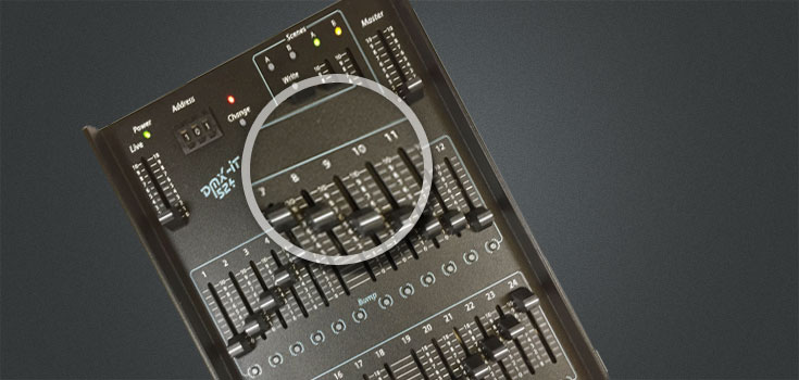
DMX-IT products needing repairs will be charged a flat rate of $75 plus $10 for ground service return shipping.
All payments must be made in advance by:
- Including a check for payment with the unit shipped from the customer
- Pre-paid by PayPal (Credit Cards accepted) PayPal account not required
PayPal payments must include customer name.
All units sent for repair must be accompanied by:
- $85 flat rate payment for repair service including return ground shipping
- The customer name, return shipping address, telephone and email contact information
- A description of the problem and/or damage
- Instructions and shipping account information for return service other than ground shipping
NOTE: Units with extensive mechanical damage will be assessed and quoted prior to repair - please provide daytime contact information. If you have special shipping needs or other questions, please call us.
For all repairs, ship to:
Integrated Controls Inc.
2851 21st St.
San Francisco, CA 94110
Designed and manufactured in USA by Integrated Controls Inc.
Prices, specifications, features and availability subject to change without notice
- Details
- Written by: Super User
- Hits: 9861
|
TESTIMONIAL
Thanks for getting back to me so quickly. Your product is working out extremely well for me.
|

|
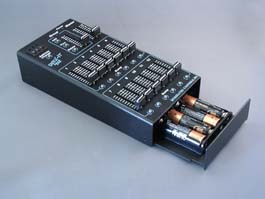
The battery box is easily accessed by loosening one screw and sliding out the battery tray. Screw and tray remain captive - no parts to drop! |
|
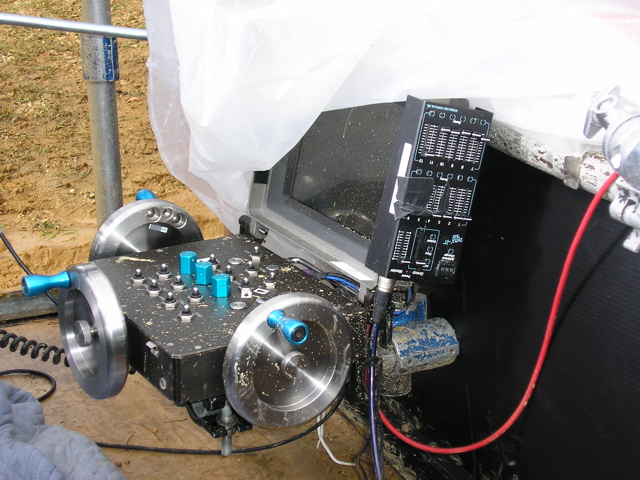
Email us photos showing your DMX-IT lighting controllers in action for inclusion on this web page. |
|
Designed and manufactured in USA by Integrated Controls Inc. |
|
- Details
- Written by: Super User
- Hits: 14162
|
Using the Bump Buttons
The Bump buttons are used to flash an individual channel to the level of the master fader. Holding the Bump button on is the equivalent of pushing the channel fader all the way up.
Using the Group Memory Feature
Group is a list of channels controlled by the Group slider. Any of the 512 channels may be assigned to the Group. The list may contain ranges of channels or individual channel numbers, and is useful for creating washes or having control independently from the other channels. Create and edit a Group using the push wheel settings, then Add, Delete and Thru switches. If a channel is assigned to the group and is also included in the manual section, the higher level is output. Add: Adds individual channels to the list. Delete: Removes individual channels from the list Thru Adds or deletes a range of channels. To delete the entire Group from memory, set the push wheel address to 9XX
Examples of Group command sequences and resulting channel group control:
*THRU must be pressed while the Group LED is still lit.
NOTE: After assigning channels to the Group slider, the push wheel indicator may not show the current starting address for the 12 manual sliders. You may want to set it back to the starting address that you last set as a reminder. This will assure that your starting address does not inadvertently get changed. Pushing the Address Change switch again is not necessary.
Designed and manufactured in USA by Integrated Controls Inc. 2851 21st St. |
- Details
- Written by: Super User
- Hits: 21680
DMX512 is a digital control signal for entertainment lighting. The DMX512 protocol standard is defined by USITT, the United States Institute for Theatre Technology. The control signal is generated from lighting control consoles and sent to dimmers and other accessories. Prior to the DMX512 protocol, analog control systems were used; zero to ten volt analog was one common standard. DMX512 is a digital multiplexing technique that uses a two conductor shielded data cable to control up to 512 dimmers. Analog systems require a wire for each dimmer channel.
The connector standard for DMX512 is a 5 pin XLR. Lighting controllers and consoles output DMX512 data on a female 5 pin XLR. Dimmers and receiving equipment often have both male XLR's for receiving and female XLR's for looping the DMX512 data to the next device. The XLR with male pins always receives and the XLR with female pins always sends.
The wire for DMX cable must be data cable designed for EIA485. This cable is low capacitance, twisted pair, shielded, and designed for high speed data. There are many brands and types that will work reliably. Standard pre-built cables can be purchased from any theatrical lighting supplier. Conversion to 3 pin XLR and use of microphone cable is known to be problematic and not recommended.
The pinout for the five pin XLR connector is:
|
Pin 1 |
Cable shield wire. |
|
Pin 2 |
Data Not (also called - Data) |
|
Pin 3 |
Data (also called + Data) |
|
Pin 4 |
spare - not used per standard - not connected in DMX-IT products |
|
Pin 5 |
spare - not used per standard - not connected in DMX-IT products |
|
Shell case |
The XLR connector body does not get connected to the cable wire |
The DMX512 data signal requires termination at the final connection in the DMX control signal loop. Improper termination is the most frequent cause of DMX problems. A terminator is a resistance at the end of the DMX line. This resistance prevents the DMX data signal from reflecting back down the line and causing data errors and other problems. DMX receiving equipment should have a "termination" switch or termination option for end of line in the setup. The data signal should only have one termination at the end of the loop, multiple terminations will load down the data signal. If the receiving equipment does not have a built in terminator, then an XLR terminator accessory should be used at the last female XLR "DMX out or loop" connector in the data line connections.
Designed and manufactured in USA by Integrated Controls Inc.
Prices, specifications, features and availability subject to change without notice


